
My program generates the appropriate waveform from the LCCDE of the oscillator.Ĭhoice = input('Choose one of the following or type 999 to quit.\n 1. The user is simply asked for the sampling frequency and oscillating frequency.
#Filter designer matlab generator#
Specifying the gain of the oscillator is irrelevant in this case because the oscillator is a waveform generator rather than a filter. The result is a neat printout of each particular filter’s LCCDE based on the user’s specified parameters. I input the standard form of each LCCDE into MATLAB as a string that calls upon my impulse response vectors to obtain the proper coefficients. Also, the user is prompted to enter a value of r for each filter and given restrictions (0 = r 1).ĭerive the LCCDE from each filter’s impulse response by converting from the z-domain to the discrete domain (n-domain).

The derivations for each filter were done by hand and vectors containing the n-domain values were entered into MATLAB.

Values of r closer to 1 (closer to each zero) will result in a narrower notch or resonator. The IIR notch, all-pole, and pole-zero resonator all have poles lying at the same angle as their zeros but at distance of r 1 from the origin.
#Filter designer matlab code#
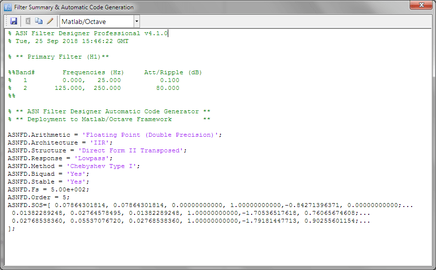
The resulting z-domain equation can be easily converted to the discrete vector and made causal by multiplying by a power of z. The matlab code below designs a bandpass filter which passes frequencies between 4 kHz and 6 kHz, allowing transition bands from 3-4 kHz and 6-8 kHz (i.e. To derive an impulse response for a filter, one must first plot the zeros of the filter on the unit circle (r = 1) in the complex z-plane. The default gain at FG of each filter is computed and then normalized to obtain the user’s desired gain at FG. FG is normalized by the sampling frequency and converted to radians to obtain w0. The user will be warned if FS does not exceed twice F0, for this does not satisfy the Nyquist theorem and will result in an inaccurate response.Īdditionally for the notch filters and resonators, the user is allowed to specify the gain in dB at a particular frequency of the filter (FG). For oscillators, the user can set the sampling and oscillating frequency. The LCCDE of each filter is output to the user along with a graph of the respective frequency response or waveform.%įor each filter the user is able to specify the sampling frequency, FS, and, F0, the frequency to be notched in the case of FIR or IIR notch filters, or resonated in the case of all-pole or pole-zero resonators. Based on user input of desired parameters, MATLAB will generate the appropriate linear constant coefficient difference equation (LCCDE). The goal of this project was to create a MATLAB program to automate the design of notch filters, resonators, and oscillators.


 0 kommentar(er)
